
I recently listened to an interview of Eben Upton on The Life Scientific podcast, where he talked about what lead to his development of the Raspberry Pi (RPi), a fully functioning computer that you can buy for as little as $5. The concept of a computer that was essentially disposable fascinated me, and I decided to get one to play with. Originally, I was going to get the cheapest model, but in order to use it, one needed to have a wireless keyboard (which I didn't have). Since I was hoping to run the computer entirely with junk that I had lying around the house, I opted instead to get the $35 model 3B, which has 4 USB 2 ports, a standard size HDMI connector, and an Ethernet connector in addition to built-in WiFi and Bluetooth. I was able to use a micro SD card, a mouse, and a keyboard that I already had, although I did have to pay about $15 more at WalMart to get an HDMI to VGA adapter in order to use an old monitor that I had stored down in the basement.

I was able to use an old iPad USB power supply to provide the power to the RPi, but it barely puts out the minimum required current, so I frequently see the little lightning bolt in the upper right of the screen indicating that the computer was being underpowered. At one point, I also used a junky USB cable and it caused the computer to infinitely re-boot until I replaced it with a better quality one.

After the initial euphoria of successfully downloading the Linux OS (known as Raspbian) onto the micro SD card and booting the computer, I realized that I didn't have the stuff that I needed to actually do the interfacing. In the past, I would have just made a trip to Radio Shack to pick up the items I needed, but since there is no longer any store in Nashville that sells electronics components to consumers, I had to make a careful assessment of what I needed so that I could make a minimal number of purchases online and save on shipping. In the following section, I'll list the items that I decided I needed.
Useful stuff for interfacing the Raspberry Pi
One of the most basic things that anyone who wants to play with interfacing the RPi should have is a solderless breadboard. I already had one, so I didn't need to order one, but if you don't have one, you need to get it. The size isn't that important because we aren't going to be hooking up a lot of things. In this post, I'm going to assume that the reader knows how to use a breadboard. If not, just read about it online. It's not complicated.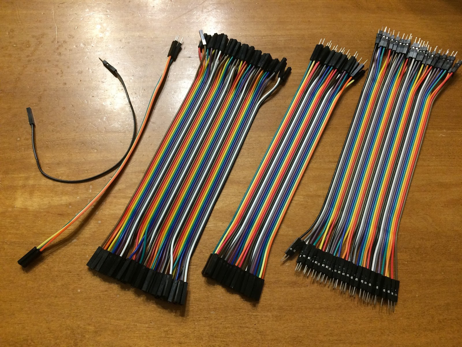

For output, the optoisolator LED is turned on by the GPIO interface and the controlled device is turned on by the phototransistor. For input, the optoisolator LED is turned on by the external sensor and the transistor is used to change the voltage present on the GPIO pin. This means that all kinds of bad things (such as over-voltaging or excessive current) can happen on the external side without having any effect on the Raspberry Pi. The worst-case scenario is that the optoisolator will get fried. Since they only cost me 35 cents each (a bag of 20 for $7), that's no big loss. The part number that I bought was AE1143, but there are probably others that are equivalent. However, if you want to use them in a breadboard, be sure that the ones you buy have a normal DIP package (see picture above) that will fit in the breadboard holes.

If the only thing you want to do is output, you don't need to buy the discrete optoisolators I described above since they are already included on this board. But if you also want to do input from sensors to the RPi, you should buy the separate optoisolators. (I'm not going to describe how to do input in this post, but it isn't very complicated.)

So if you already have a monitor, keyboard, USB power supply, etc. to hook up the computer, and if you already have a breadboard, your total cost to get off the ground with the RPi computer, relay module, and parts necessary to connect them is about $60 (plus whatever you have to pay for shipping).
Important issues relating to interfacing the Raspberry Pi
Although the Raspberry Pi provides a great opportunity for learning electronics, I already had enough experience with electronics that I wasn't really looking at this project as a means to increase my knowledge in that area. Mostly, I just wanted to turn things on and off with the minimal amount of effort. So of course, I started by googling topics related to interfacing an RPi.Unfortunately, most of the results fell into two categories: questions asked by people who knew little or nothing about electronics that were answered by people who also didn't really know much about electronics, or highly technical questions asked by people who knew a lot about electronics that resulted in technical answers given by electrical engineers. Neither of these kinds of sources of information really told me what I wanted to know: the most straightforward way to safely turn things on and off using the RPi GPIO pins.
After consulting a number of online sources, I reached some conclusions, which I will summarize below. I should also say that I found the book "Exploring Raspberry Pi : Interfacing to the Real World with Embedded Linux" by Derek Molloy (John Wiley & Sons, Incorporated, 2016. ) very useful as a comprehensive reference. The book went far beyond where I was interested in going, but there were two sections that were particularly helpful. The general introduction to the GPIO (pgs. 220-223) and the introduction to digital input and output to powered circuits (pgs. 224-229) provided pretty much all of the technical details I needed to safely start interfacing without having to worry about frying the RPi.
Pins on the GPIO
One of the most important details is knowing the purpose of the 40 pins of the GPIO. Fig. 6-1 (p. 221) of the Malloy book is probably the best diagram I've seen, but since I don't have permission to post it here, I'll instead include a diagram from https://pinout.xyz/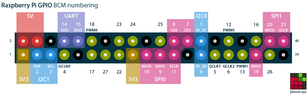
The orientation of the pins in this diagram correspond to the orientation shown in the close-up image of the RPi shown earlier in this post. There are two numbering systems for referring to the pins. One refers to the physical position of the pin. That system starts with 1 at the lower left, 2 at upper left, 3 lower 2nd column, 4 upper 2nd column, 5 lower 3rd column, etc. to pin 40 at the upper right. The other numbering system, which is probably more commonly used, is the "GPIO" number. I believe that this numbering system is consistent with earlier models of RPi that had fewer than 40 pins. In the diagram above, the GPIO numbers are shown above and below the pins (e.g. GPIO14 and GPIO15 in the upper row of pins, 4th and 5th pins from the left). In the default operating mode, any of these numbered GPIO pins can be used for input or output, with the exception of the ID_SD and ID_SC pins numbered 0 and 1 in this diagram. You should not connect anything to these pins unless you do further research into their function. Various pins can serve purposes (indicated by the color highlighting) other than general input and output when the GPIO is put into other modes, but that is beyond the scope of this post.
Power from the GPIO
In the diagram above, there are 12 pins that don't have GPIO numbers. The 8 black-colored pins are ground pins. They are all equivalent. The two red-colored pins labeled "5V" can provide power at 5 volts, and the two tan-colored pins labeled "3V3" can provide power at 3.3 volts. These pins provide a convenient source of power for things that you've connected to the GPIO pins, but they have a limited power output. Your circuit should not draw more than 200-300 mA from the 5 V source and should draw no more than 50 mA from the 3.3 V source.
You should make sure that when the RPi is turned off, there is no power being applied to the GPIO pins. That's not a problem if you are using only the built-in power supply from the 5.0 and 3.3 V pins because they'll power down when the RPi powers down. If your circuit needs more current than what the built-in power supply can provide, you should provide an external power supply. But it's best that such externally-powered circuits be electrically isolated on the other side of optoisolators anyway so that you don't have to worry about them accidentally applying power to the GPIO pins of the turned-off RPi. It is good to use the internal GPIO power pins only for parts of the circuit on the computer side of the optoisolators.

Turning on an LED with a GPIO pin
There are abundant examples on the web showing how to turn an LED on and off using one of the GPIO pins set in output mode. Essentially, when the GPIO pin is set to "on", it outputs 3.3 volts and when it is set to "off", it is at ground. To turn on and off an LED, you simply place an LED in series with a resistor and connect the ends to the GPIO pin and one of the ground pins. (If you put the LED in backwards, nothing bad happens - just turn it around and try again.) The resistance of the resistor should be low enough that the LED lights up enough to see, but not so low that the circuit draws more than 2-3 mA from the 3.3V output of the GPIO pin. A 1 k ohm resistor should be OK for that purpose. (If you are only turning on a single LED, you can make the LED brighter by using a smaller resistor and draw more than 3 mA from a GPIO pin. But you don't want to do that with multiple pins at once.) I chose to use GPIO pin 18 because it was conveniently located next to a ground pin.
There are a number of ways to use software to turn a GPIO pin on and off. Since I planned to use Python to write the controlling software, I imported a module called "gpiozero" that has a simple function for turning a GPIO pin on and off. (There are other more sophisticated Python modules for interacting with the GPIO, but that's beyond the scope of this post.) Here's the code:
from gpiozero import LED
from time import sleep
led18 = LED(18)
led18.on()
sleep(5)
led18.off()
The program makes GPIO18 go to 3.3 volts (turning the LED on), waits for 5 seconds, then makes GPIO18 go to 0 volts (turning the LED off). This was pretty exciting for about the first minute or so after I got it to work, but it wasn't really what I was trying to accomplish: turning any device on and off.

Wikimedia Commons, Optoisolator_Pinout.svg
However, if you look at the circuit diagram of an optoisolator, you can see that the left side is simply an LED. So the simple task of turning on an LED is really useful if that LED is inside an optoisolator. Following the example of Fig. 6-7 (p. 228) of the Malloy book, I connected pin 2 of the optoisolator to one of the GPIO ground pins, connected a resistor of about 2 k ohm to pin 1 of the optoisolator, and connected the other end of the resistor to the GPIO pin that I wanted to use to control the circuit (e.g. GPIO18). (Note: pin 1 is designated by a small dot on the top of the optoisolator DIP.) Based on Fig. 6-7, that should result in drawing a safe current of about 1 mA from the GPIO pin.
Turning something on and off with an optoisolator
The phototransistor side of the optoisolator is essentially a switch. When sufficient light comes from the LED inside the optoisolator, current flows from pin 3 to pin 4. When the LED is dark, no current flows. However, the amount of current that flows through the phototransistor is pretty small when the LED is lit with only 1 mA of current. So the phototransistor can be used to turn on another transistor in one of two ways:
Wikimedia Commons, left: Darlington_pair_diagram.svg CC BY-SA by user Michael9422, right: Compound_trans.svg
The transistor pair on the left is called a Darlington pair and the pair on the right is called a Sziklai pair. In both pairs, the transistor on the left (Q1) would represent the phototransistor inside the optoisolator. Instead of being controlled by current flowing into its base (B), Q1 is controlled by the light from the LED striking it. In the Darlington pair, Q2 is an NPN transistor, which is turned on by current flowing into its base. So when the phototransistor Q1 turns on, the small current flowing from it into the base of transistor Q2 is enough to saturate Q2, causing a lot of current to flow through Q2 from its collector (C) to its emitter (E). In the Sziklai pair, Q2 is a PNP transistor, which is turned on by current flowing out of its base. So when the phototransistor Q1 turns on, the small current flowing through it pulls enough current from the base of transistor Q2 to saturate Q2, causing a lot of current to flow through Q2 from its collector (C) to its emitter (E).
Either of these two configurations produces the same result: turning on the phototransistor in the optoisolator turns on a second transistor that can sink a lot more current. The current sunk by the second transistor is enough to turn on a small light, or to energize the coil of a relay. If the thing that you want to turn on and off is something that draws a lot of current, uses a voltage higher than about 5 volts, or uses alternating current, then you will need to use the second resistor to turn on a relay. A relay is a mechanical switch that is closed when its coil is energized. Since the switch is mechanical, it doesn't care about the nature of the electricity passing through it as long as the voltage and current don't exceed the maximum for which it is rated. So for example, if you want to turn the lights of your house on and off, you'll need a relay since the voltage is over 100 volts and is alternating current. (Note: I do NOT advise that you try this unless you are familiar with the safety hazards associated with household wiring. You can electrocute yourself if you make a mistake.) You also should use a relay if you want to control any kind of motor.
Turning the 8-relay module on and off
If you don't care about how the electronics work and just want to put the relay circuit together, skip this section.This kind of setup is exactly what is built into the 8-relay module that I bought online. Sunfounder has a useful page that provides a helpful circuit diagram of the 8-relay module. From that page, you can download a large scale circuit diagram as well as a wiring diagram of the module. I've pulled out the circuit diagram for one of the relay modules:

If you compare this diagram to the ones above, you'll see that the central part of the circuit is a Darlington pair. The load that is turned on by the NPN transistor T5 is a relay, shown in the upper right of the diagram. When the coil is not energized, pin 1 of the relay is connected to pin 2. When the coil is energized, pin 1 is connected to pin 3 of the relay. Thus, the relay is a single pole, double throw (SPDT) switch. The diode D5 is there because when a coil is de-energized, its collapsing magnetic field can generate a surge of current that can damage the transistors, so the diode allows that current to safely dissipate.
According to what I've read online, you should be able to connect the input of the relay module directly to one of the GPIO pins and use it to turn the relay on and off. The "testing experiment" for Raspberry Pi on the Sunfounder page shows how to do this. But I would NOT recommend that you try that experiment for several reasons. The most obvious reason is that the photos on the web page do not show clearly how to connect the wires (some wires hide others, making it hard to tell what's going on). The other reason why following the pattern in that example is a bad idea is because it uses the Raspberry Pi's power supply to run everything. In their example, they get away with it, but if you are really planning to use the relay module to power 8 devices, you need to have a better understanding of how to make the connections in a safe way that doesn't risk over-voltaging or drawing too much current from the GPIO connections.
The first issue with the Sunfounder example circuit involves using the RPi's 5 volt power pin to run everything, including the LEDs shown on the circuit board. In real use, the load driven through the relays would be powered separately, using any possible voltage and current that the relays are rated for. The particular relays in the module say that they can handle up to 10 A, AC voltages up to 250 V, and DC voltages up to 30 V. For my testing, I connected a little battery-powered motor to pins 1 and 3 so that the motor would turn on and off. That circuit should have no connection to anything else on the circuit board.
The other issue is whether the voltage supply pins labeled "VCC" and "JD-VCC" should be tied together and supplied with a single power supply, or if they should be supplied with power separately. When the relay unit ships, it comes with a jumper that connects VCC and JD-VCC pins:

The circuit diagram shows that JD-VCC supplies 5 volt power to the transistors and coils of the relays. When the relays aren't energized, the current is minimal, but when a single coil is energized, it draws about 65 mA. So if you were only going to use one of the 8 relays, you could easily use the 5 V power pin from the RPi GPIO pin set to supply the power. However, if you used three relays and they were routinely energized at the same time, you would be approaching the 200 mA limit of output for the 5 V GPIO power pin. Using all 8 relays would draw over 500 mA, which would probably either fry or at least crash the RPi. In addition, if like me you are running the RPi off of an iPad charger/power supply that barely provides enough current to run the RPi even without interfacing, you might crash the RPi with even fewer than 3 relays connected. A relatively simple solution is to just create your own battery-operated power supply using 4 D cells and a voltage regulator. That could easily run the relay unit for a pretty long time, and by being battery powered would enable you to use it in a robot without having to have a cord plugged into a wall receptacle. See the Appendix at the end for more on this.
The other problem with the relay board is that the inputs are "active low". That means that they are turned on when the GPIO pins are "off" (at ground = 0 V). To turn the relays off, the GPIO pins controlling them need to be "on" (3.3 V). Since the GPIO pins starting state is "off", that isn't really a good thing, because it means that the coils on the relay board would be energized as soon as the RPi is turned on - before you even start running the software to control it. It would be better to make the inputs be "active high" so that the coils would only be energized when you send a signal to make them be energized (i.e. turn the GPIO state to "on"). I became aware of this issue while reading a thread on the raspberrypi.org forum. I don't recommend reading the thread unless you are really hard-core, because the thread really gets out into the weeds and the suggested solution involves hooking up a bunch of discreet transistors and resistors to solve the problem.
There is actually much simpler solution that has been mentioned in several other places: using a ULN2803APG chip (the last item on the list of supplies that I bought for this project). You can view the data sheet for the ULN2803, but I'll cut to the chase by inserting the circuit diagram here:

You can ignore all of the resistors and diodes and just focus on the two transistors. If you compare this diagram with my earlier diagrams, you'll see that the ULN2803APG contains a Darlington pair. When the input of the ULN2803APG goes "high", current flows into the base of the transistor on the left, turning it on. Current flows from its emitter into the base of the second transistor, turning it on - effectively closing a switch that connects the output to ground, i.e. making the output "low". If the output is connected to the input of one of the relay controllers, it will ground the relay input, causing both the LED inside the optoisolator to turn on and the indicator LED on the relay circuit board to turn on.
When the input of the ULN2803APG goes low, both transistors turn off, disconnecting the output from the ground and allowing its voltage to float. If the output is connected to the input of one of the relay controllers, it will be at the VCC voltage and the optoisolator won't be turned on.
The combination of resistors inside the ULN2803APG was chosen so that the output goes low when the input exceeds 2.5 volts (just right for the GPIO output voltage of 3.3 V).
So essentially, the ULN2803APG chip flips the inputs of the relay board to make them active low rather than active high. That function is shown symbolically in the pinnout diagram for the ULN2803:

The wiring configuration is super simple. For each relay that you want to control, connect the output of the GPIO to one of the bottom pins on the chip (1 through 8), then connect the pin on the opposite side (11 through 18) to the input on the relay board that you want to control. The GND pin needs to be tied to one of the ground pins on the RPi and to the ground pin on the relay board. It does not seem to me that it should be necessary to connect the "COMMON" pin to anything, although in the examples I've seen it's been connected to VCC of the relay board. I don't think it matters, since under normal operation the diode on the common connection will block any current from flowing anyway.
The only remaining question is what power source to use for the VCC connection on the relay board. If one created an external 5 V power supply (such as the one I suggested using D batteries), that supply could be used. However, in the spirit of keeping the RPi completely isolated electrically from external circuits, it would probably be best to connect the VCC connection on the relay board to one of the 5 V power pins on the GPIO since the VCC connection supplies the computer side of the optoisolators. In my test circuit, I found that the ULN2803APG chip drew a negligible amount of current when connected by itself to the 5 V pin (as expected given the diode in the "common" connection inside the chip). When the VCC pin of the relay board was connected to the 5 V pin of the GPIO, it only drew about 1.3 mA per relay control circuit. So even if all 8 relays were in use, it would draw only about 10 mA from the 5 V pin - way below the 200 mA maximum "safe" output for that pin. I didn't actually measure the current being drawn from the GPIO control output pin, but I would imagine that it would be at a safe, low value since it is only turning on the transistors on the ULN2803APG, and not actually driving the optoisolator and status LEDs on the relay board as it would have been if there were a direct connection from the GPIO to the relay board.
After all of the stress I encountered trying to figure out a "safe" way to run the 8-relay module from the RPi GPIO, I'm pretty satisfied because this setup is both really simple to wire and also keeps the currents and voltages on the GPIO pins far below their safety limits. If a separate 5V supply is used to power the relay coils via JD-VCC (rather than using a 5 V power pin from the GPIO), the RPi is also completely isolated electrically from external circuits on the far side of the optoisolator.
Quick and dirty instructions for connecting the 8-relay board to the Raspberry Pi
It is best to make the initial connections with the RPi turned OFF in case you plug a wire in the wrong place during the setup.1. Remove the jumper connecting the VCC and JD-VCC pins on the 8-relay board and leave it off.


4. Use a jumper wire to connect the GND pin of the ULN2803APG chip to the GND pin of the 8-relay board (it doesn't matter which GND pin).
5. Use a jumper wire to connect one of the 5 V pins on the Raspberry Pi's GPIO (it doesn't matter which of the 5 V pins) to the common pin of the ULN2803APG chip.
6. Use a jumper wire to connect the common pin of the ULN2803APG chip to a VCC pin on the 8-relay module (it doesn't matter which VCC pin).
7. Connect a jumper wire from the GPIO output pin that you want to use to one of the input pins on the ULN2803APG chip. If you want to use the code in my example, use GPIO18 (pin 12). Using pin 11 on the ULN2803APG chip would be sensible.
8. Connect a jumper wire from the corresponding output pin of the ULN2803APG chip to the input of the relay that you want to use on the 8-relay board. If you used ULN2803APG pin 11 in the last step, you should use pin 18 for the output pin.
9. Connect the JD-VCC pin on the 8-relay board to a 5 V source of power. If you just want to test the system with a single relay, you could connect it by a jumper to a 5 V power pin of the RPi's GPIO (or to the common pin of the ULN2803APG chip, which is itself connected to the 5 V pin). But don't do this if you are going to use more than 2 or 3 of the relays (see details above for the reason). In that case, buy or make a separate 5 V power supply to supply JD-VCC (see appendix).
10. Turn on the Raspberry Pi and your external 5 V power supply (if you used one).
11. Run the code snippet that I gave above if you are using Python (you must first have first imported the gpiozero module). For other programming languages, look up appropriate code on the web. If everything is working, you should see the indicator LED for your chosen relay turn on for 5 seconds, then turn off. If you listen carefully, you should also be able to hear a quiet clicking sound as the relay closes and opens.
12. If everything has worked up to this point, connect something that you want to turn on to the relays. You'll need a jeweler's screwdriver or some other small screwdriver to open the screw that clamps down on the output wires from the relay. A small, battery-powered motor is good for a test. Here's how it worked for me: https://twitter.com/baskaufs/status/963243621012123648
Froggy the Robot, take 1


In the end, we had a little Visual Basic program with buttons that sent a number whose bits determined which relays should be turned on and off. Each bit of the output of the UART went through a 7404 TTL NOT chip (to prevent backwards frying of the UART chip and to invert the signal), and the output of the 7404 drove a PNP transistor in a manner very analogous to Sziklai pair discussed earlier in this post.
One difference between the relays that we used in our project and the relays that come on the 8-relay board is that the relays in our robot project were double pole, double throw (DPDT) rather than SPDT. The reason this was important to us was that we wanted to use the relays to be able to reverse the direction of the robot motors. See this diagram that I borrowed from quora.com:

Our robot was not very sophisticated - it just had 2 wheels whose direction could be controlled independently. When both wheels went forward, the robot went forward. When both went backwards, the robot went backwards. When one wheel went forwards and the other went backwards, the robot rotated in an appropriate direction (we had a third unpowered caster wheel to support the back side of the robot platform).
The most exciting feature of the robot was an old drawer from a CD drive (back in the days when they were motorized). With two more relays, we could power the drawer motor and control its direction (in or out). The out-and-in movement of the drawer reminded my daughters of a frog's tongue, so that's how the robot got the name "Froggy". In the end, my daughters created a game where a magnet hung from the end of the "tongue" and they could drive the robot around picking up small iron BBs scattered on the floor.
After the novelty wore off, Froggy was put away in a box. Between then and now, serial ports have virtually disappeared from computers, although I was able to get my old Dell laptop running long enough to make this video of the old Froggy in operation:
Froggy the Robot, take 2
When I decided to buy a Raspberry Pi, I knew immediately that one of my first projects would be to try to rebuild Froggy to be controlled directly by the RPi GPIO interface. All of the parts of Froggy's brain that ran the UART could be lobotomized, leaving the board with the relays and all of their connections to the motors. In the part of this diagram:where the NOT gate was, I replaced it with the collector side (pin 3) of the phototransistor in one of the discrete optoisolators. Pin 4 was connected to a common ground with the coil. I was a bit concerned whether the phototransistor could sink enough current to light up the indicator LED as well as turning on the PNP transistor that drove the relay. But it had no problem with that, so I was rather quickly able to run the five control wires for the relays into the outputs of 5 optoisolators.
The most difficult part of making the conversion was to make a cable to connect Froggy to the RPi. When I ran Froggy with the RS232 interface, it only required two wires (a ground wire and the signal wire). I was able to splice together several old telephone cords to make Froggy's teather quite long. However, when controlling Froggy using the RPi, I needed a separate control wire for each of the five relays, plus a ground wire. Luckily, I was able to find an ancient ribbon cable that had been spliced to a multi-wire cable, which I had salvaged from some old piece of junk. It had only narrowly escaped being thrown out last summer when I cleaned out the basement. Unfortunately, there were more wires in the multi-wire cable than in the ribbon cable, and apparently some of the ribbon cable wires weren't actually connected to anything. So I had to spend over an hour with my ohmmeter trying to figure out which of wires at the two ends of the cable were actually connected to each other. Eventually, I had something like 10 usable wires in the cable - 6 for running Froggy now and some others for future expansion.
Here is the end result:
You can see the Python code that runs the Froggy controller in this gist.
Future projects
I probably won't devote a lot of energy to embellishments for Froggy. I may add one or more sensor buttons to the end of the tongue that will detect if the robot has run into something. In this post, I didn't go into how to accept input through the GPIO interface. It is much simpler than output and only requires 5 V power, an optoisolator, a resistor, and a switch. I may write another post if I get sensor buttons working.What I really want to do is to figure out how to set up a web server on the RPi so that I can communicate with it through WiFi and the Internet. If I manage to do that, the RPi will just ride on Froggy with a portable power supply - no monitor, keyboard, or mouse required. If I get that to work, I could control the robot through a remote computer or perhaps my phone. We'll see if I ever get around to doing that!
Appendix
To run Froggy's onboard 5 V electronics, I just bought a little MC78LXXA 5 volt (positive) 0.1 A positive voltage regulator (TO-92 package). It was super-simple to hook it up. Here's a diagram of a different 5 V voltage regulator, but the concept is the same.
I bought a D cell holder that would hold 4 cells in series. At 1.5 V per cell, that's 6 volts. I connected the negative end of the cell holder to the ground pin of the voltage regulator and the positive end to the "+5.5V ... 16V" connection at the left side of the diagram. The "+5V" connection at the right serves as the regulated 5 V supply (with a common ground to the negative end of the battery holder. My data sheet says "Bypass Capacitors are recommended for optimum stability and transient response and should be located as close as possible." I actually just left them out and got away with it, although it probably would have been better to have put them in.
The MC78LXXA is rated for an output of 100 mA. I suspect that when I was driving all 5 of the relays, I might have gone over that, but it always was able to run the circuitry anyway. When the robot is at rest with no energized relays, I don't think that it is drawing more than about 10 mA. If you wanted to use the 4 D cell system to provide power to the 8 relay module, I think you could just use a 5 volt regulator with a higher current output rating. For example, I googled and found a μA7805CKC regulator in a TO-220 package that is rated at 1.5 A. That would easily provide the 500 mA that I estimated was required when all 8 relays on the module were energized, with 1000 mA to spare.